8.8 Thin section process
1 Prepare related components and connecting wires
1.1 Prepare related components *The following is for reference only.Customers need to prepaer relevant devices according to actual needs

2 Software opening and loading steps
2.1 Software opening and loading steps Power on the robot control system, enter the robot control system, open and load the software as per the following:
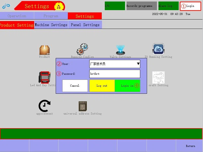
① Login (Remark: Open the Login page)
② User (Remark: Select "Manufacturer Technician" in User)
③ Password (Remark: enter "brtbrt" in the password box)
④ Login in (Remark: Click "Login in")
⑤ Settings (Remark: Click "Settings" when the robot system is in the stop mode)
⑥ Product Settings (Remark: Select "Product Settings")
⑦ craft Setting (Remark: Click "craft Setting")
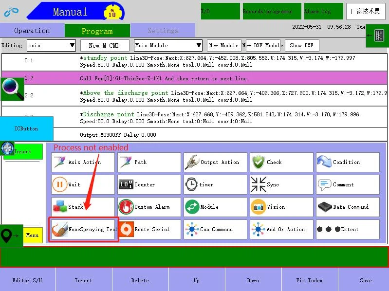
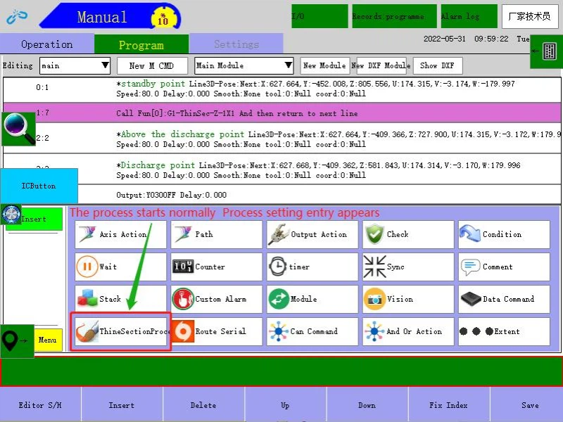
⑧ Technology type (Remark: Select "ThinSectionProcess" to proceed to the next step)
⑨ Some technology takes effect after rebooting


3 Function meaning and command introduction

3.1 Definition explanation of thin section process parameters
① G1~G4: Support 4 groups of thin section; 4 groups can be set at the same time, and their start points are independent and do not affect each other
② Start Pos: Set the start point to grab the first section; you can try running the current start point after setting in
③ X Count: Number of stacks in X direction, X Count × Y Count = total number of stacks
④ Y Count: Number of stacks in Y direction, X Count × Y Count = total number of stacks
⑤ Plane Sel: Confirm the direction in which you need to run exp, X, Y or Z
⑥ X Space and Y Space: The spacing distances in X and Y directions between each stack and next stack
⑦ EXP Len: Max exp distance at each time
⑧ M. EXP Len: The absolute distance from the first section to the last section in the current stack
⑨ Seq X->Y and Y->X: Fill in the sequence in which you want to run multiple stacks; in case of 1 stack, no sequence.
⑩ SP Speed: The start point speed at which the stack is run
⑪ F. EXP Speed: The speed for returning to the start point of the stack and fast exp
⑫ S. EXP Speed: The speed at which the EXP Len is executed
⑬ D. Offset: The height difference between the first piece and the last piece
⑭ Output Config: Used to set the current Y-type general output in IO board, corresponding to O.F.B.E setting
⑮ Input Config: Used to set the current general input in IO board, generally used for find signal.
⑯ O.F.B.E: After it is ticked, the robot runs to the start point and outputs the set specified IO.
⑰ C.S.E.F: If the exp fails, switch to the next stack and pick the material again. (Remark: If not ticked, after exp fails, alarm will not be given, and re-exp will be performed; if exp still fails after reaching M. EXP Len, alarm will be given. If ticked, after each exp failure, alarm will be given
⑱ Save: After it is clicked, a fixed module will be generated according to the current craft setting
3.2 Thin section process command and definition explanation


① Plane: 0
Explanation: 0, 1, 2 respectively correspond to Z, Y, X
Seq: 0
Explanation: 0 and 1 are X->Y and Y->X respectively
X Count: 1 Y Count: 2
Explanation: Total number of stacks = X × Y, namely 1×2=2 stacks
EXP Len: -3 Explanation: Each exp is performed at a distance of -3mm
M. EXP. LEN: 3
Explanation: The max distance of down exploration is 3
Output: 16|0.0; Input: 2|0
Explanation: The 17th Y port is output Y30: delay 0S; the 3rd X port is input X12: find ON (0 - ON; 1 - OFF)
Start Point
Explanation: The world coordinates of the start point of thin section process
SP Speed: 50
Explanation: The percentage of program line speed at which a program runs back to the start point
Fast Exp Speed: 30
Explanation: The percentage of program line speed at which a program performs fast exploration
Slow Exp Speed: 10
Explanation: The percentage of program line speed at which a program performs normal slow exploration
D. Offset: 0
Explanation: The height difference between the first piece and the last piece is 0
O.F.B.E: true
Explanation: If ticked, automatically output IO when running the exp path
C.S.E.F: false
Explanation: If "unUse" is ticked, after exp fails, alarm will not be given, and re-exp will be performed; if exp still fails after reaching M. EXP Len, alarm will be given.
ThinGroup-3
Explanation: The third group of thin sections is used
② Stop action: Start find IO:X12ON stop current action
Explanation: After execution, if there is X input signal in the running process, the machine will immediately stop and jump to "End find"; however, all the remaining contained output and flags will become effective
③ Stop action: End find IO:X12
Explanation: Combined with "Start find", as the find end point
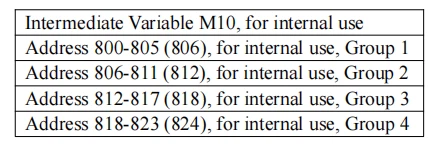
Remark: Output occupied internally by thin section process and address table
4 Use flow
1. After the robot is fitted with end sucker jigs, open ThinSectionProcess in the menu bar 
2. Set Group 1-4 thin section start point according to the product placement situation. The following example is about Group 1 Thin Section: move the end sucker jigs of the robot above 1 stack of sections, align at the pick center, and set in "Start Point"
3. Set total number of stacks to 1, namely X=1 and Y=1
4. Set "Plane" to Z (set "Plane" according to the actual product placement position, and support the settings of Up and Down, Left and Right, Front and Back)
5. Set "X Space" and "Y Space" (spacing distance between corresponding stacks; in case of 1 stack, set to 0)
6. Set "EXP Len" to 3 (The setting reference here is based on the current thickness of the product; the value is more than 1 or more times of the thickness; as long as it's safe, avoid exp failure due to too short or extrusion due to too long; this should be set based on the actual application situation
7. Set "M. EXP Len" to 10 (slightly higher than the total height from the first thin section to the last thin section)
8. Set "Seq" to X->Y (fill in the sequence in which you want to run multiple stacks; in case of 1 stack, no sequence).
12.Set "SP Speed" to 50 (fill in according to the actual situation)
13.Set "F. EXP Speed" to 30 (fill in according to the actual situation)
14.Set "S. EXP Speed" (fill in according to the actual situation)
12. Set D. Offset to 0 (in case of 1 stack, as long as there is a height difference, it can also be filled in)
13. Output Config: Write in Y30; user can customize the setting according to the actual situation
16.Input Config: Write in X12; user can customize the setting according to the actual situation
17.Tick "O.F.B.E"
17,If "C.S.E.F" is not ticked, user can customize the setting according to the actual situation 17. After clicking "Save", inert new module as production process program module


19.The program generation is finished, and the module is automatically entered

19. Insert the generated module in main program for normal use.
5 Instruction example mold program
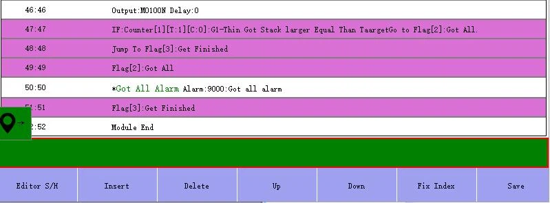
The example is to instruct the thin section process of stack 1 product

Display of program lines in Generate Program module


8.9 Description of 380V additional axis for drive and control integrated system
*Safety Precautions ★ Do not touch the terminal within 15 minutes after the power is cut off; otherwise, electric shock might occur
1 Select additional axis modules
The current high-power drive and control integrated 380V additional axis modules support motors with a max power of 2.9KW+0.75KW or less. Select appropriate additional axis modules according to the power requirements

2 Install servo module
2.1 The robot returns to null point and back up ghost
To avoid accidental loss of the origin or data of the robot, the robot should return to the origin and back up ghost before removing the module.
2.2 Move I/O module
After cutting off the power and standing more than 15 minutes, remove additional axis closure plates, remove I/O module, move in the heavy duty wire direction to the reserved hole on I/O module, fix I/O module with lock screws (avoid pulling the network wire or I/O module power wire during movement. First remove the wire notch cover and take out the wire).
2.3 Install additional axis modules
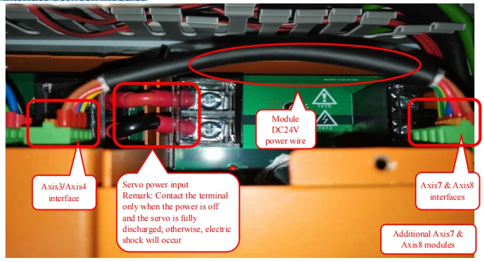
Insert the prepared additional axis modules between Axis3/Axis4 and I/O module, and install additional axis brake relays (DC24V).

2.4 Connect power, communication and brake wires between modules
2.4.1 Power wire interface between modules
2.4.2 Communication/brake wire interface
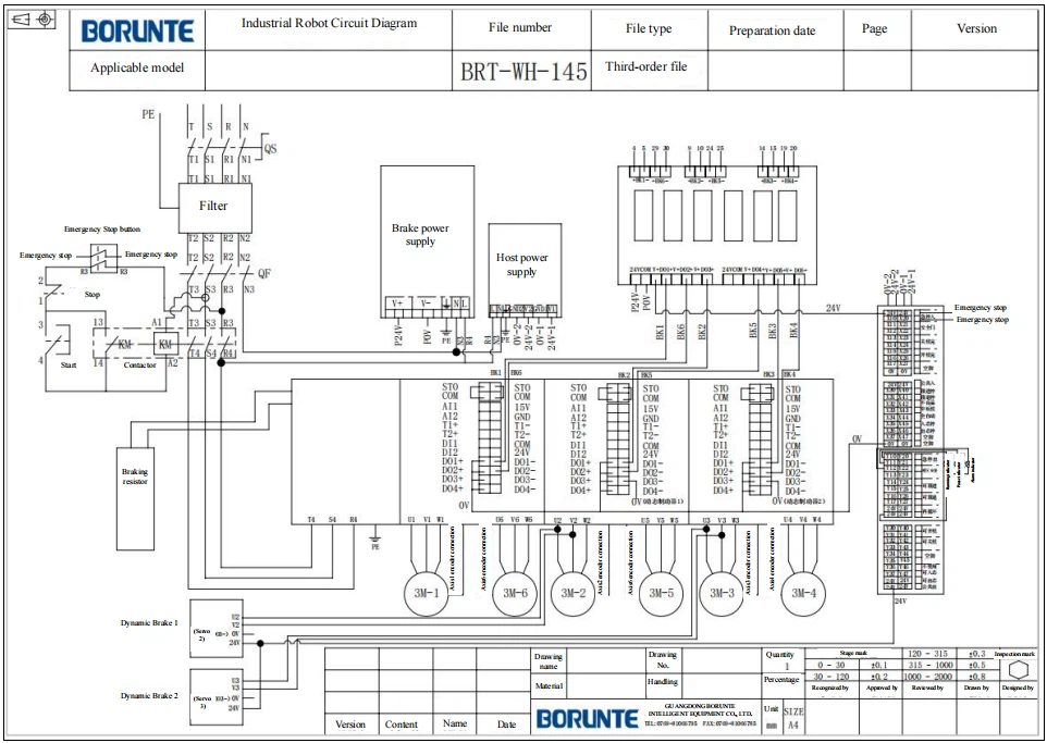
STO and COM need to be short-circuited by short connecting wire; DO1+~D04+ need to be connected to power 0V, and belong to the same module as brake relay or dynamic brake; the sequence of communication wires must be correct (I/O module → Axis7/Axis8 IN, J7/ Axis8 OUT → Axis3/Axis4 IN, Axis3/Axis4 OUT → Axis2/Axis5 IN, Axis2/Axis5 OUT → Axis1/Axis6 IN).

3 Additional axis connection
3.1 Encoder/power wire bonding definition

3.2 Encoder/power wire interface Axis8 encoder interface Axis8 encoder interface Axis7 encoder interfaceAxis7 encoder
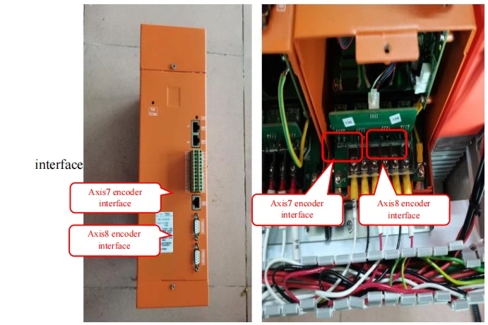
4 Additional axis setting Login permission → Settings → Product Settings → craft Setting → set "Axis Num" to 8 → power off and restart the drive and control integrated electric box

5 Motor parameter setting
5.1 Axis7 motor parameter setting

5.2 Motor mapping setting
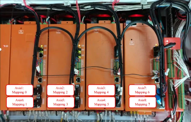
5.3 Axis8 motor parameter setting
Refer to Axis7 motor settings and fill in the mapping address according to the actual.
6 ResetSII After setting the motor parameters, turn the demonstrator key to the stop position → click "About" (diagnostic message) at the bottom right of the motor demonstrator screen → click "ResetSII" → Wait about 2 minutes for factory reset and then power off and restart.


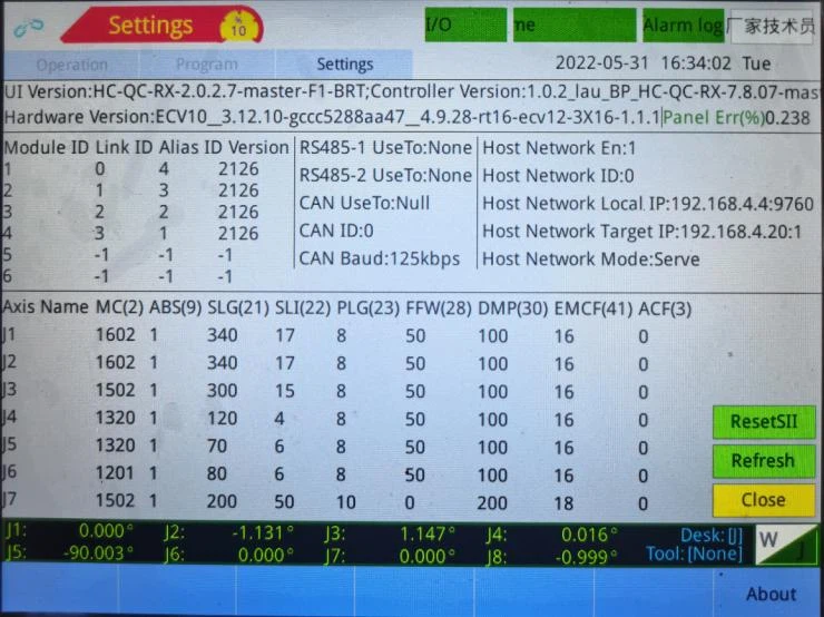
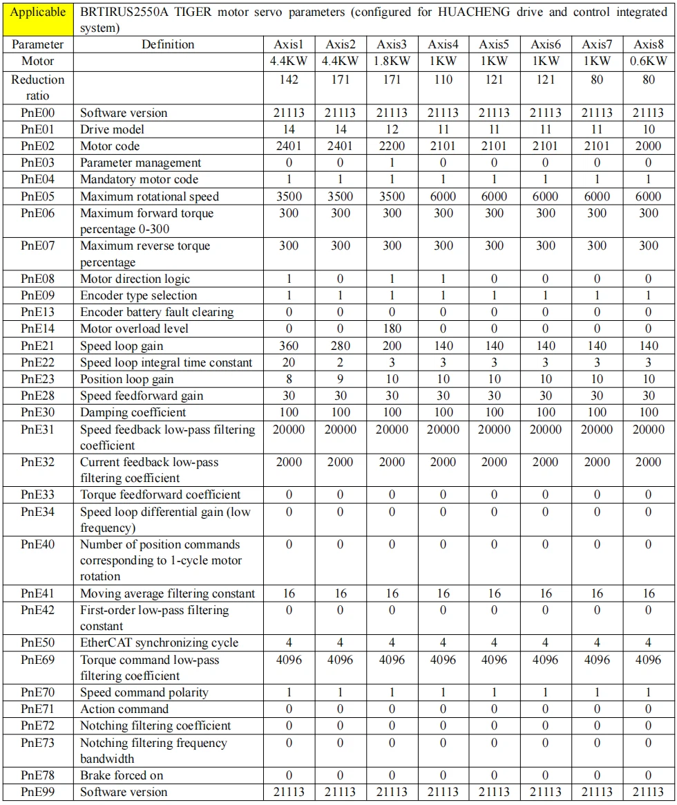
Appendix: Servo Settings Reference
The following are the servo settings of BRTIRUS2550A with additional J7 & J8 (For reference only. Reduction ratio, gain and other parameters need to be adjusted according to the actual situation on the site).
